TREZOR Model T Dev Kit

Introduction

This hobbyist project documents a kit that developers can use to explore, develop, test, and debug the open source TREZOR Model T hardware and software.

Warning

This kit does NOT produce a production TREZOR Model T cryptocurrency hardware wallet device.

If you want an official TREZOR Model T hardware wallet, see: https://shop.trezor.io/

When contrasted to official production hardware, this kit is less safe to use for non-development purposes.

Necessarily, different selections were made for key security properties of this developer kit vs. production hardware. For example, when used as documented here, this kit purposefully leaves debug capabilities enabled, and does not apply write protections to boardloader flash memory. This is so that developers may repeatedly develop, test, and debug all types of changes.

Production hardware irreversibly disables debug capabilities and Device Firmware Upgrade (DFU) mode, and protects key memory areas as part of reducing attack surface and increasing depth of defenses. There may be other subtle, yet meaningful, weaknesses as well, depending on your usage and threat model.

This kit is not a perfect analog to the actual production hardware. It uses a very similar, yet different MCU (STM32F429ZIT6 vs the Model T's STM32F427VIT6). Certain features, for example the ability to reset the touch panel independently from the display, are not made available on the display module used by this kit. There are other differences such as the display driver chip not being the same as the one used in production Model T devices (we support both driver chips in the code). But, this kit is "close enough" and comprised of easily obtainable, relatively inexpensive, off-the-shelf components which allowed it to be developed alongside, and actually used for development of the production Model T.

USE THIS KIT AT YOUR OWN RISK

Hardware

TREZOR Model T Open Source Hardware Reference Documentation

A nice thing about this kit is that it was used to openly develop the TREZOR Model T. Due to that there is already some detailed documentation about the kit available at the link above. The purpose of this document is not to duplicate that documentation, but rather to detail how to put the kit together and use it. Please reference the TREZOR Core hardware documentation for the latest information.

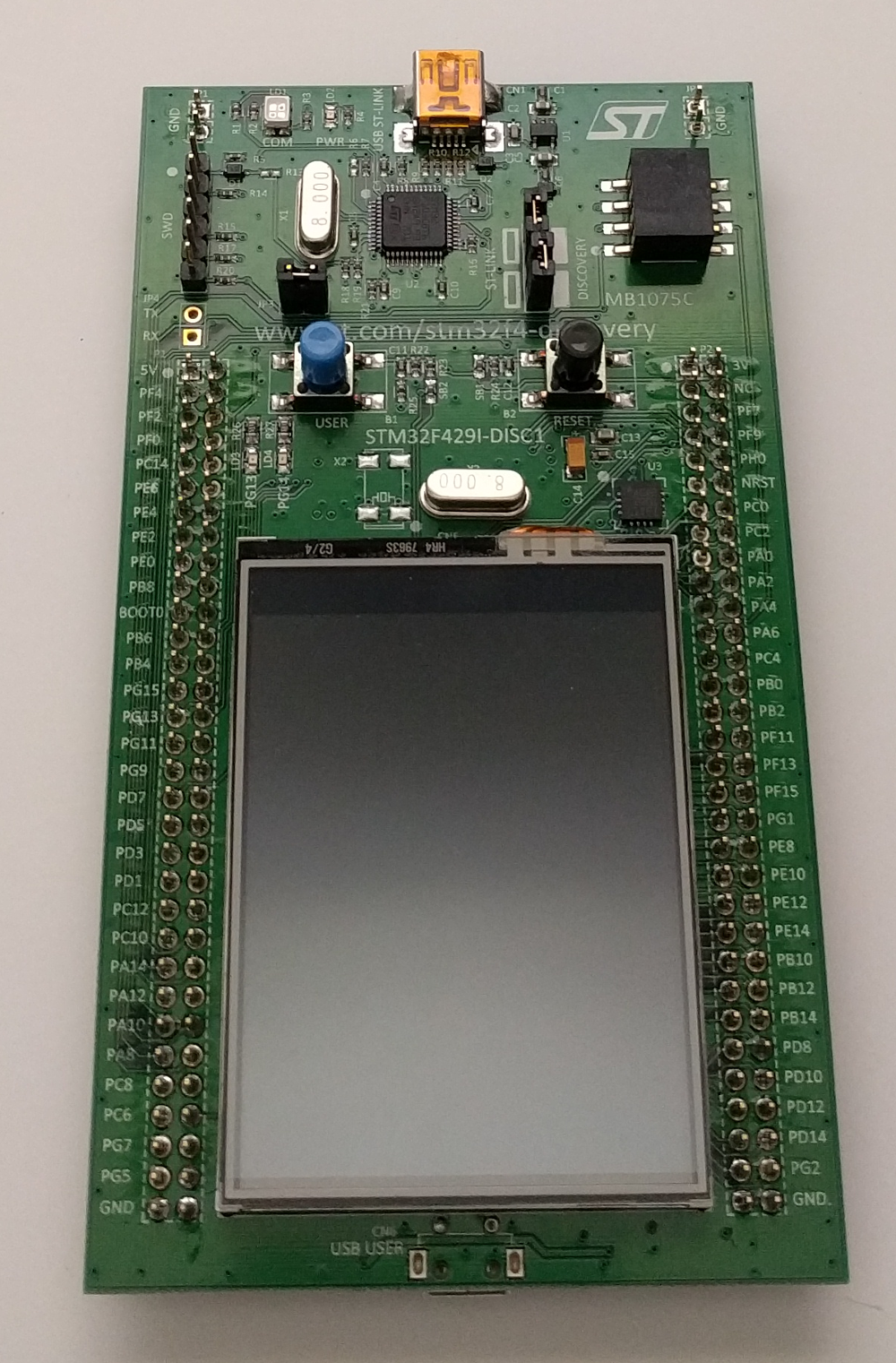
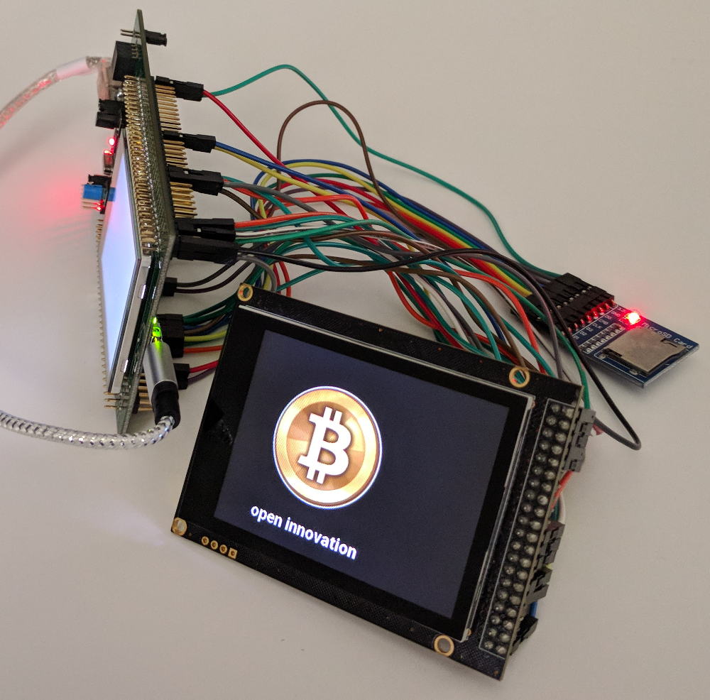
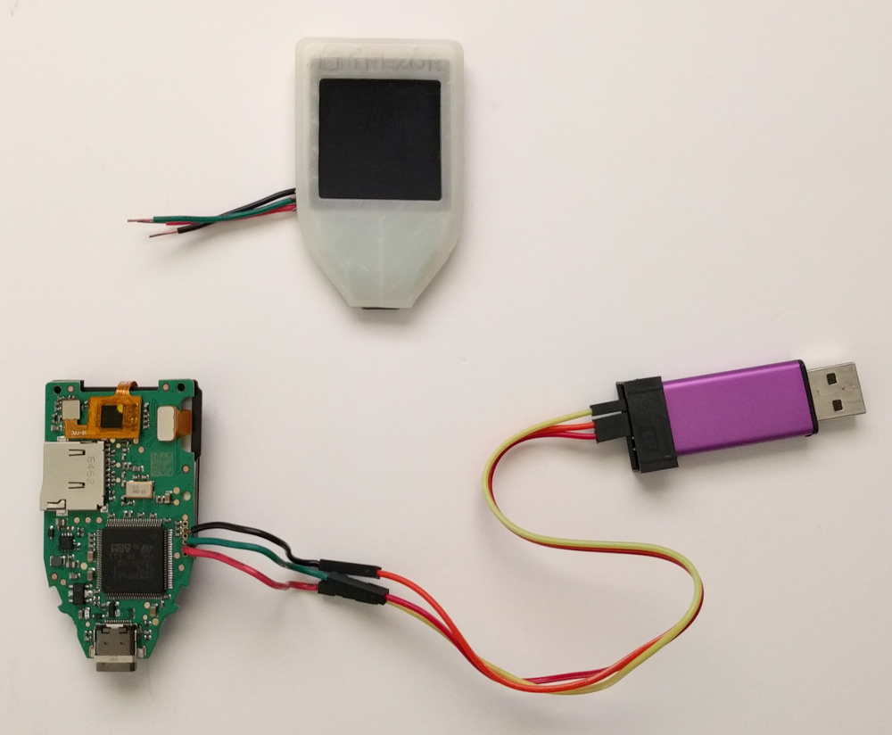
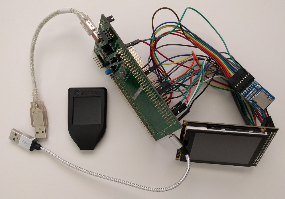
Here's what the completed kit looks like:

The completed kit shown alongside a Production TREZOR Model T for scale
Fig H1. - The completed kit shown alongside a Production TREZOR Model T for scale. This is one of the actual kits used to develop the Model T software. Coincidentallly, the photo kind of looks like a parent giving its child a hug.

The completed kit (bottom)
Fig H2. - The completed kit (bottom)

Setup

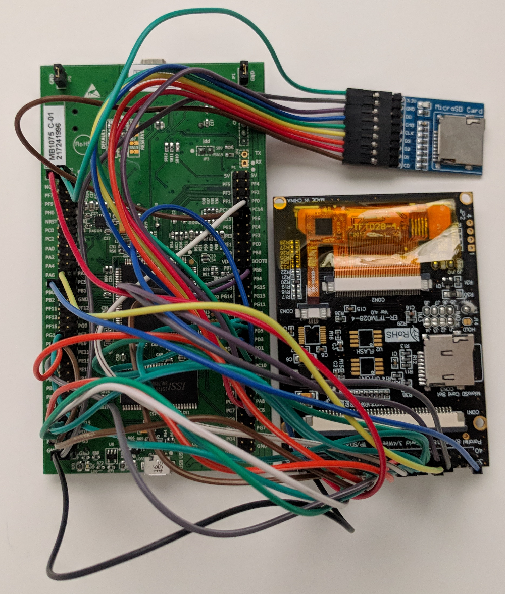
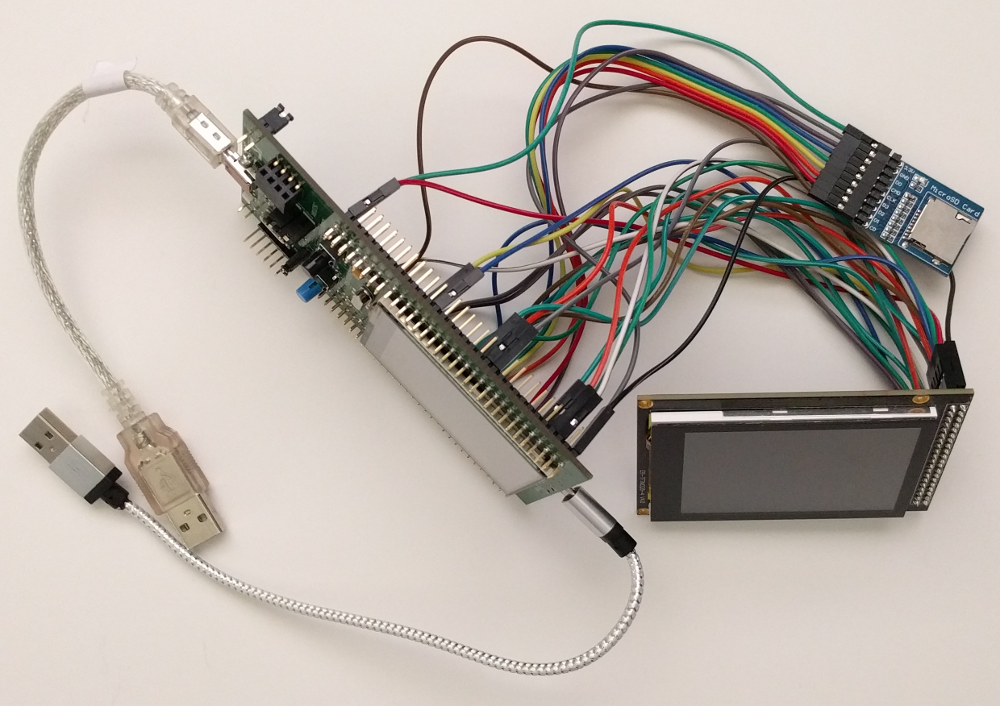
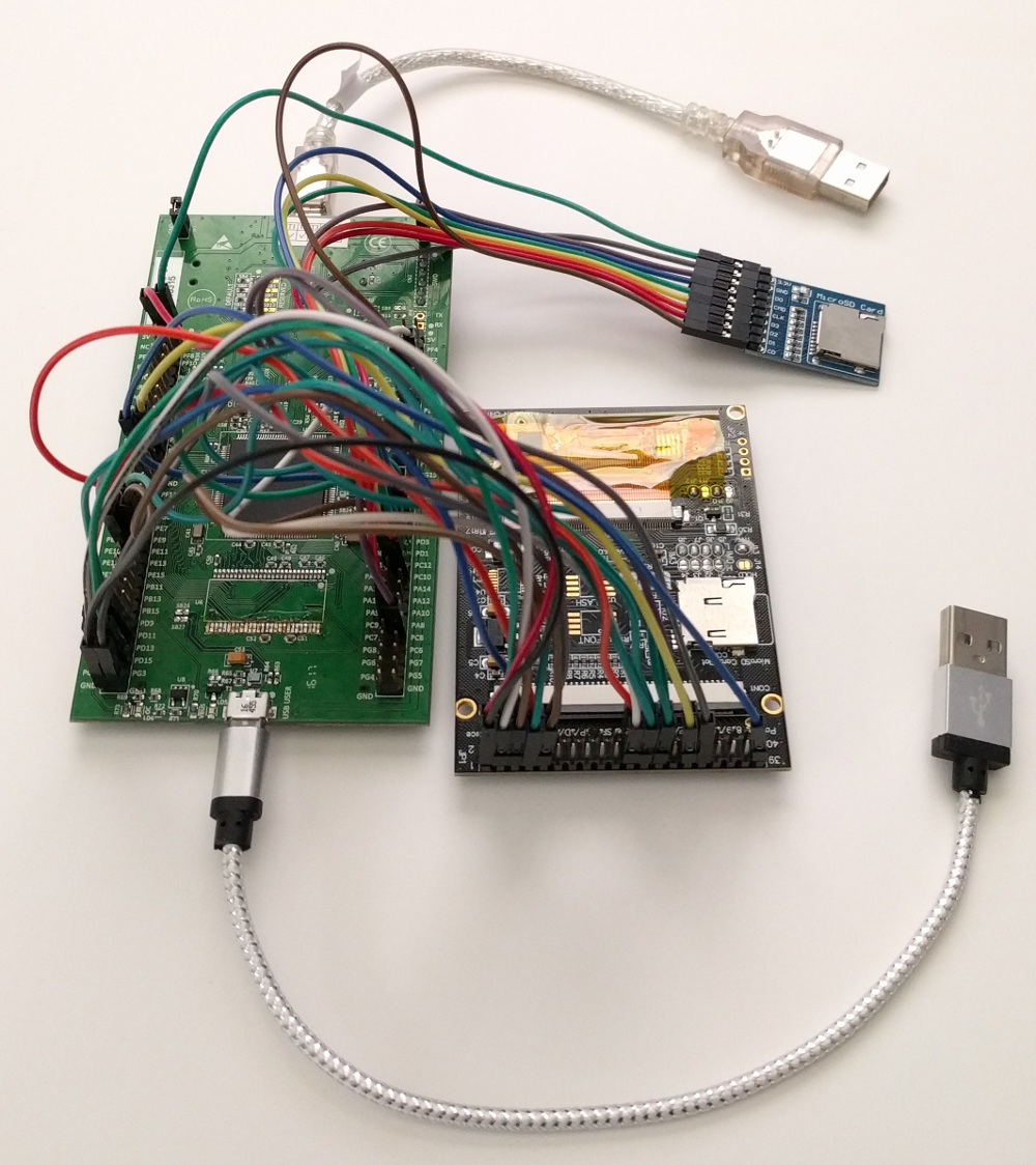
Wiring the Dev Board

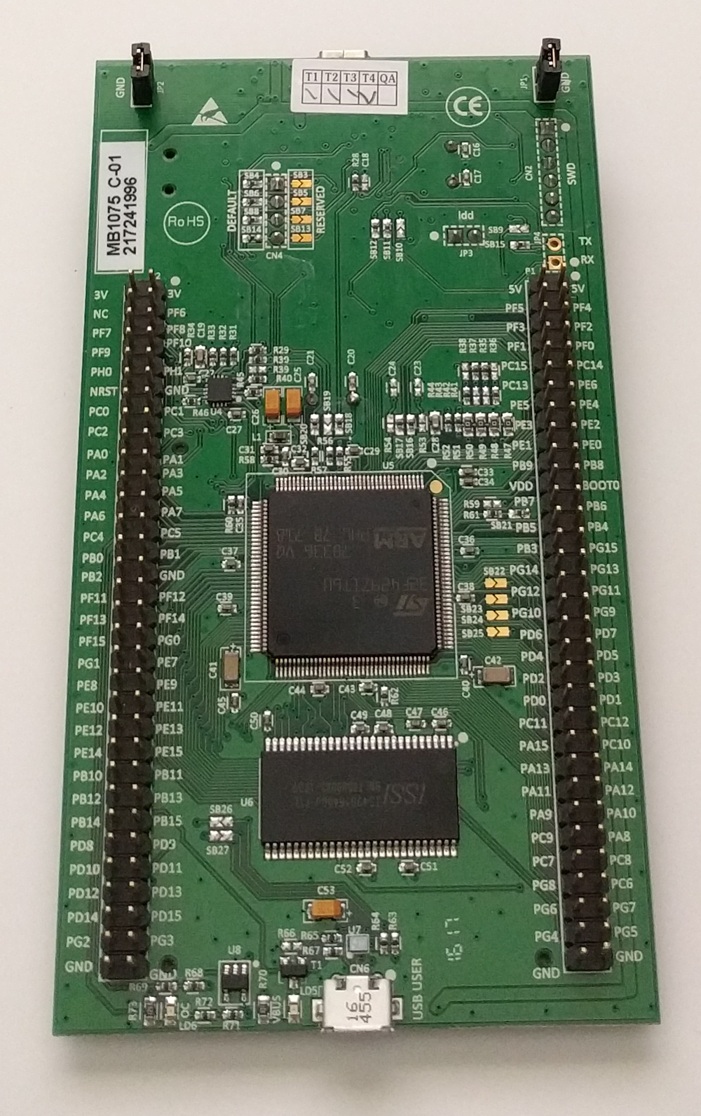
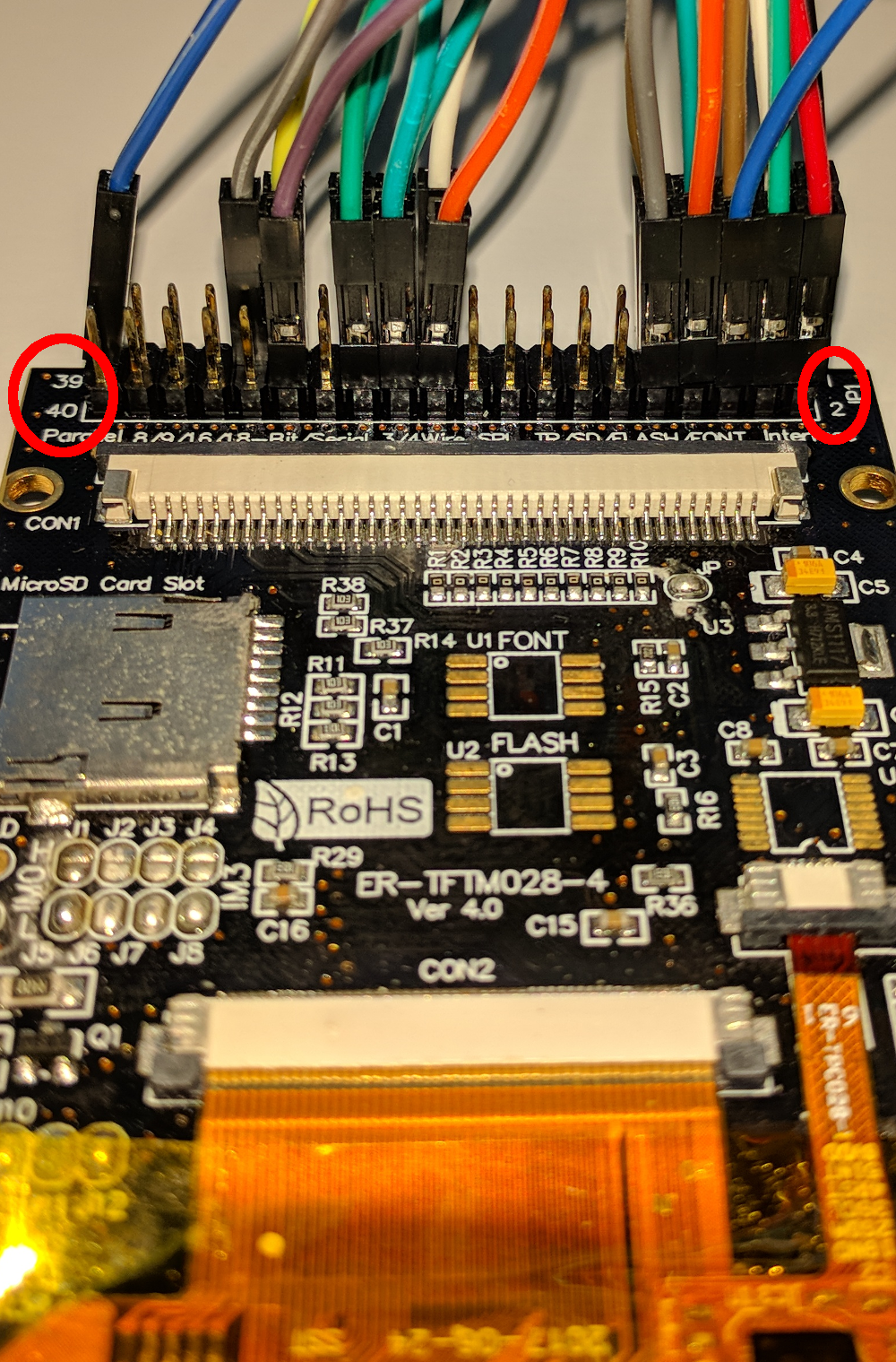
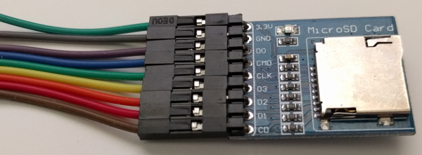
First, be sure to set the jumpers as seen in Fig H3 and Fig H4. Second, go through the pinout tables for the display and the touch panel and put wires on the dev board pins (aka MCU pins) that have a corresponding display module pin noted in the tables. If you need help finding the dev board pins that map to the display module, see Fig H9 and Fig H10. Next, connect the wires over to the correct display module pin. The display module pins are numbered 1 through 40 (see Fig H5). All you need to do is connect the wires as stated in the pinout tables. Finally, add wires to the microSD socket as shown in Fig H6 and use the silkscreen on the microSD socket as your guide to connect those wires over to the dev board pins as specified in the microSD socket pinout table. When you've completed the wiring, you'll have something that looks like Fig H7. Plug-in the USB cables, and you're done (Fig H8).

The dev board as it first arrives (top)
Fig H3. - The dev board as it first arrives (top)
The dev board as it first arrives (bottom)
Fig H4. - The dev board as it first arrives (bottom)
Note the display module pin numbering guides on the left and right sides of the 40 pin header (39, 40, 1, and 2)
Fig H5. - Note the display module pin numbering guides on the left and right sides of the 40 pin header (39, 40, 1, and 2)
Note the microSD socket silkscreen pin guides
Fig H6. - Note the microSD socket silkscreen pin guides
Display module and microSD socket wiring complete
Fig H7. - Display module and microSD socket wiring complete
Display module and microSD socket wiring complete with USB cables attached
Fig H8. - Display module and microSD socket wiring complete with USB cables attached
Dev board to display module wiring (side 1)
Fig H9. - Dev board to display module wiring (side 1)
Dev board to display module wiring (side 2)
Fig H10. - Dev board to display module wiring (side 2)

Software

TREZOR Model T Open Source Software Main Repository

Setup

This setup process comprises steps to install development and debugging tools on a temporary computer, then build and install a boardloader, bootloader, and firmware on the kit's MCU.
The following setup process was documented while running an Ubuntu 18.04 LTS Desktop (Bionic Beaver) Live CD as user ubuntu.

  1. Connect to the Internet
  2. cd /tmp/
  3. Install required software packages
    • sudo add-apt-repository universe
    • sudo apt-get update
    • sudo apt-get -y install git openocd make scons python3-dev python3-pip cython3 libusb-1.0-0-dev libudev-dev libssl-dev protobuf-compiler libprotobuf-dev
    • sudo -H pip3 install pipenv trezor[ethereum,hidapi]
  4. Download tools
    • GNU ARM Embedded Toolchain
      • wget https://developer.arm.com/-/media/Files/downloads/gnu-rm/7-2018q2/gcc-arm-none-eabi-7-2018-q2-update-linux.tar.bz2
  5. Extract tools
    • tar xjf gcc-arm-none-eabi-7-2018-q2-update-linux.tar.bz2
  6. Add extracted tool binaries to PATH environment variable
    • /bin/echo 'export PATH="/tmp/gcc-arm-none-eabi-7-2018-q2-update/bin:$PATH"' >> ~/.bashrc
    • source ~/.bashrc
  7. Setup udev rules to make the USB devices available to non-root users
    • /bin/echo -e '# 0483:df11 STMicroelectronics STM Device in DFU Mode' > /tmp/99-dev-kit.rules
    • /bin/echo -e 'SUBSYSTEM=="usb", ATTR{idVendor}=="0483", ATTR{idProduct}=="df11", MODE="0666"' >> /tmp/99-dev-kit.rules
    • /bin/echo -e '# 0483:3748 STMicroelectronics ST-LINK/V2' >> /tmp/99-dev-kit.rules
    • /bin/echo -e 'SUBSYSTEM=="usb", ATTR{idVendor}=="0483", ATTR{idProduct}=="3748", MODE="0666"' >> /tmp/99-dev-kit.rules
    • /bin/echo -e '# 0483:374b STMicroelectronics ST-LINK/V2.1 (Nucleo-F103RB)' >> /tmp/99-dev-kit.rules
    • /bin/echo -e 'SUBSYSTEM=="usb", ATTR{idVendor}=="0483", ATTR{idProduct}=="374b", MODE="0666"' >> /tmp/99-dev-kit.rules
    • /bin/echo -e '# 534c:0001 SatoshiLabs Bitcoin Wallet [TREZOR]' >> /tmp/99-dev-kit.rules
    • /bin/echo -e 'SUBSYSTEM=="usb", ATTR{idVendor}=="534c", ATTR{idProduct}=="0001", MODE="0666"' >> /tmp/99-dev-kit.rules
    • /bin/echo -e 'KERNEL=="hidraw*", ATTRS{idVendor}=="534c", ATTRS{idProduct}=="0001", MODE="0666"' >> /tmp/99-dev-kit.rules
    • /bin/echo -e '# 1209:53c0 SatoshiLabs TREZOR Model T Bootloader' >> /tmp/99-dev-kit.rules
    • /bin/echo -e 'SUBSYSTEM=="usb", ATTR{idVendor}=="1209", ATTR{idProduct}=="53c0", MODE="0666"' >> /tmp/99-dev-kit.rules
    • /bin/echo -e 'KERNEL=="hidraw*", ATTRS{idVendor}=="1209", ATTRS{idProduct}=="53c0", MODE="0666"' >> /tmp/99-dev-kit.rules
    • /bin/echo -e '# 1209:53c1 SatoshiLabs TREZOR Model T' >> /tmp/99-dev-kit.rules
    • /bin/echo -e 'SUBSYSTEM=="usb", ATTR{idVendor}=="1209", ATTR{idProduct}=="53c1", MODE="0666"' >> /tmp/99-dev-kit.rules
    • /bin/echo -e 'KERNEL=="hidraw*", ATTRS{idVendor}=="1209", ATTRS{idProduct}=="53c1", MODE="0666"' >> /tmp/99-dev-kit.rules
    • sudo cp /tmp/99-dev-kit.rules /etc/udev/rules.d/
  8. Download, build, and flash the TREZOR Model T boardloader, bootloader, and firmware from source code to the kit's MCU
    • Plug both of the USB cables from the dev board into your computer's USB ports.
    • git clone https://github.com/trezor/trezor-core.git
    • cd trezor-core/
    • make vendor
    • pipenv install
    • pipenv run make clean vendor build_boardloader build_bootloader build_firmware flash openocd_reset STLINK_VER=v2-1 OPTIMIZE=-Og
  9. Attach a debugger to the kit
    make openocd STLINK_VER=v2-1
  10. Open another terminal, then connect gdb to the OpenOCD process that was started in the previous step:
    make gdb_boardloader
  11. Set some test breakpoints and practice debugging code:
    • (gdb) b *reset_handler
    • (gdb) b *main
    • (gdb) layout regs
    • (gdb) si
    • (gdb) c
    • (gdb) lay src
    • (gdb) i b
    • (gdb) d
    • (gdb) i b
    • (gdb) file build/bootloader/bootloader.elf
    • (gdb) b *main
    • (gdb) c
    • (gdb) Press Ctrl + C to interrupt software execution
    • (gdb) quit
  12. Done flashing the software to the dev board and debugging. Kill the OpenOCD process and unplug the debug adapter and dev board.
  13. Test the software just loaded onto the dev board:
    • Plug-in the dev board and progress past the unofficial/unsafe firmware warning.
    • cd /tmp/
    • git clone https://github.com/trezor/python-trezor.git
    • cd python-trezor/
    • git submodule update --init --recursive
    • python3 setup.py prebuild
    • ./trezorctl wipe_device
    • ./trezorctl reset_device -t 256 -r -p -l 'open innovation' -s
    • ./trezorctl backup_device
    • ./trezorctl get_address -c Bitcoin -t address -n "m/44'/0'/0'/0/0"
      (note: this is a legacy base58 encoded p2pkh)
    • ./trezorctl get_address -c Bitcoin -t p2shsegwit -n "m/49'/0'/0'/0/0"
      (note: this is a base58 encoded p2wpkh-p2sh)
    • ./trezorctl get_address -c Bitcoin -t segwit -n "m/84'/0'/0'/0/0"
      (note: this is a bech32 encoded p2wpkh)
    • ./trezorctl get_address -c Litecoin -t address -n "m/44'/2'/0'/0/0"
    • ./trezorctl get_address -c Litecoin -t p2shsegwit -n "m/49'/2'/0'/0/0"
    • ./trezorctl get_address -c Litecoin -t segwit -n "m/84'/2'/0'/0/0"
    • ./trezorctl get_address -c Namecoin -t address -n "m/44'/7'/0'/0/0"
    • Now, set a custom homescreen:
      • cd /tmp/
      • Copy the URL for one of these images and use it in the next "wget" step:
      • 144px x 144px TREZOR Model T Homescreen Image144px x 144px TREZOR Model T Homescreen Image144px x 144px TREZOR Model T Homescreen Image144px x 144px TREZOR Model T Homescreen Image144px x 144px TREZOR Model T Homescreen Image
      • wget -O homescreen.png https://mcudev.github.io/trezor-model-t-dev-kit/images/trezor-t-homescreen-btc.png
      • /tmp/trezor-core/tools/png2toi /tmp/homescreen.png
      • /tmp/python-trezor/trezorctl set_homescreen -f /tmp/homescreen.toif
    • Your kit should look something like this after completing this tutorial (note that you can swipe the screen with your finger to change its orientation). Congratulations!
      The dev board after completing this tutorial
      Fig S1. - The dev board after completing this tutorial

Questions

Bonus

Bonus Developer Information

The awesome folks at SatoshiLabs were nice enough to provide me with some prototype development boards as the Model T was being developed. This helped greatly with development because I could then code and test with the actual MCU and peripherals that were going to be used. They even sent me a prototype body which is in the photos below. These photos are included as extra bonus developer information because sometimes it is interesting and/or instructive to see the artifacts that are made and used throughout the development cycle of a product. As an external contributor, I spent a lot of time developing with the dev kit documented by this tutorial, and then switched to the prototype boards for fine tuning and testing.

Prototype dev boards. 22AWG Solid Core Hook-up Wire is used to connect to the debug adapter.
Fig B1. - Prototype dev boards. 22AWG Solid Core Hook-up Wire is used to connect to the debug adapter.
Prototype dev boards (flipped)
Fig B2. - Prototype dev boards (flipped)
Prototype dev boards (side). Display stuck to prototype board with double sided tape.
Fig B3. - Prototype dev boards (side). Display stuck to prototype board with double sided tape.
Prototype dev boards v10 (top)
Fig B4. - Prototype dev boards v10 (top)
Prototype dev boards v10 (bottom)
Fig B5. - Prototype dev boards v10 (bottom)

The ST-LINK debugger that is on the dev board can be used to debug an external application (e.g.- the prototype board). To do this, remove/disconnect the dev board's jumpers on CN4 and wire the prototype board to the dev board's SWD pins on CN2. Here is the pinout:

DescriptionPrototype Board SWD PinDebugger SWD Pin
SWD Clock (SWCLK)42
GND23
SWD I/O (SWDIO)54
Reset (NRST)15

One reason to do this is to be able to connect and debug under reset. The other pictured USB debug adapter does not support connecting under reset. Below are some photos of the prototype board wired to the dev board debugger.

Prototype dev boards v12 wired to dev board debug adapter (bottom)
Fig B6. - Prototype dev boards v12 wired to dev board debug adapter (bottom)
Prototype dev boards v12 wired to dev board debug adapter (top)
Fig B7. - Prototype dev boards v12 wired to dev board debug adapter (top)
Prototype dev boards v12 wired to dev board debug adapter (side)
Fig B8. - Prototype dev boards v12 wired to dev board debug adapter (side)